Structural Design
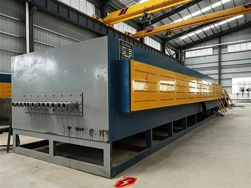
The furnace chamber is constructed from stainless steel plates, forming an enclosure for heating and hot-air circulation; the flow of hot air within the chamber significantly enhances temperature uniformity. The agitation provided by the hot air intensifies convection and heat equalization within the chamber atmosphere.
The furnace chamber and the support frame feature a decoupled design; the chamber rests on load-bearing rollers at the base of the frame, allowing for free sliding in the longitudinal direction. This enables the chamber to expand freely along its length when heated.
To prevent hot air leakage, the furnace door incorporates a dual-layer sealing system (inner and outer). The inner layer utilizes a ceramic fiber rope seal, while the outer layer employs a silicone rubber sealing ring. To extend the service life of these seals, a stainless steel cooling water jacket is integrated at the chamber opening to dissipate heat. The door locking mechanism utilizes a multi-point handwheel-operated system, ensuring uniform locking around the door's perimeter. Additionally, the door mounting assembly-attached to the chamber face-uses a movable dual-hinge mechanism that shifts in tandem with the chamber's thermal expansion, thereby ensuring a superior seal.
An exhaust stack is designed at the top of the unit to vent the large volumes of exhaust gas and smoke generated during the heating process; the exhaust flow rate can be regulated via a damper control handle.
Control System Design
The control system is integrated into the furnace body. It utilizes an intelligent programmable temperature controller, with temperature profiles managed through automatic control settings. Control outputs are generated via linear combinations of variables to regulate the process. The controller processes signals from thermocouples to modulate the power module.
Fan Placement Design
The fan is positioned at the rear of the furnace chamber. It drives air across the heating elements via a volute casing and dual side air ducts. Once heated, the air enters the chamber horizontally to heat the workpiece uniformly before being drawn back into the circulation fan through the rear intake, ensuring thorough circulation and mixing.
Airflow Deflector Design
The volute casing significantly impacts fan performance; removing it would reduce performance by more than 50%. This hot-air box furnace employs a dual-circulation configuration: the fan is located at the rear, feeding into two side circulation ducts, with the rear volute providing bidirectional airflow.
Due to space constraints within the hot-air chamber, the expansion section of the volute is relatively short and the outlet area is large, resulting in significant airflow pressure loss. When designing the volute, the shape of the guide vanes should ensure effective diffusion; an arrangement of 4 to 8 vanes is appropriate, with installation angles determined by the impeller shape and flow rate. The width of the volute should be designed to ensure there is no contact with the impeller.