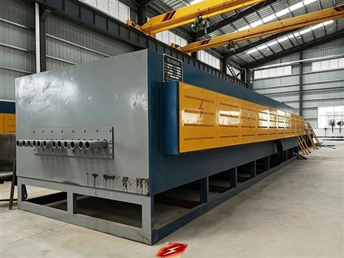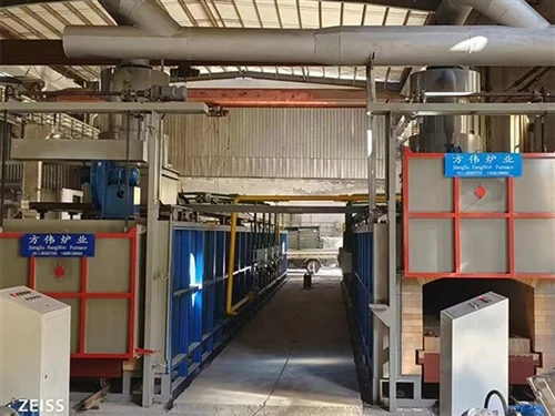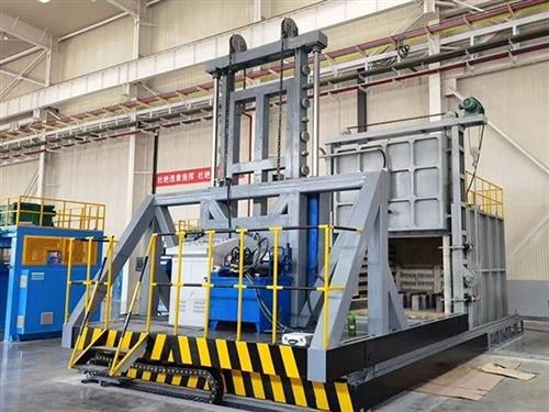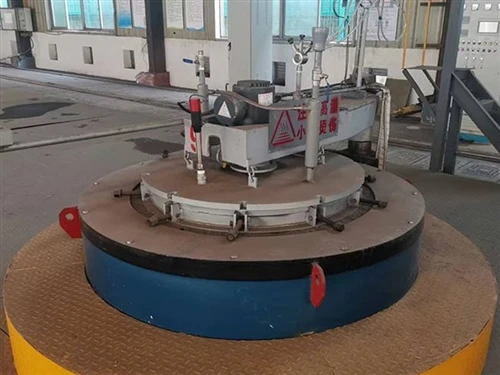
The quenching furnace consists of several components, including the furnace body, furnace door, heating elements, ventilation system, and control system.
The furnace body is fabricated from welded structural steel and steel plate; the inner lining features stainless steel plating integrated with the furnace shell, with the space between the shell and the inner chamber filled with aluminum silicate refractory fiber for thermal insulation.
The furnace door is located at the bottom of the furnace body, meaning workpieces enter and exit from below. The bottom opening is serviced by a door mechanism operated via a mechanical drive system comprising a motor, gearbox, sprockets, chains, and guide rails.
High-resistance alloy strips serve as the heating elements; they are mounted on both sides of the inner chamber using specialized hooks and are electrically insulated from the chamber walls.
The ventilation system consists of a blower fan and air deflectors. An electrical interlock connects the blower motor to the heating elements, ensuring the elements are energized only when the blower is running; this guarantees operation under proper air circulation.
The loading basket and the transfer cart are fabricated from welded structural steel and balanced for a centered horizontal gravity point; they are designed for vertical lifting.
The furnace is supplied with a loading basket and cart to ensure immediate operational readiness. During loading, the basket sits on the cart, which is moved in and out; upon reaching the position beneath the furnace, the door opens and a hoist engages the chain to lift the basket into the furnace, after which the door closes for the heating process. For unloading, the door opens and the hoist lowers the basket into a water tank for quenching; the basket is then lifted out onto the cart, the chain is detached, the hoist retracts, and the cart is withdrawn for subsequent aging treatment.
A water tank is located beneath the furnace body to allow for the rapid immersion of workpieces for quenching.
The control system utilizes components such as thyristors and digital display meters (see Figure 3) to manage temperature control and alarm functions.
Limit switches are installed on the furnace door mechanism and the loading lift mechanism; these are linked to the control cabinet's power supply. When the workpiece reaches its highest point, the circuit for the furnace door mechanism is activated, and the power supply to the heating elements is engaged. When the furnace door opens, the power supply to the heating elements is cut off, and power is supplied to the lifting mechanism to lower the workpiece for water quenching.